Lab 1: Modulation and Demodulation Techniques
Introduction
Today we are going to build a simple amplitude modulation signal with carrier signal and also attempting to demodulate the modulated signal back to the regular message signal. In layman terms, we are sending a message that would kind of look like a regular sine wave functions that can represent a message being sent from source A to Destination B. We need to modulate the signal, again, one of the big reasons we need to modulate the signal is to reduce interference of the signal as its at long distance or even short distances. Once the signal arrives to the destination, we need to reclaim the message signal. We do this by demodulating the signal, and extracting the message signal to the destination which then can be read.
To Get Started
For this lab we be using:
MATLAB
Simulink
Students should have access to MATLAB, which is under academic use. Simulink will fall under MATLAB, so you need MATLAB to download Simulink. If you need assistance on downloading this program, I would recommend contacting Engineering Technology Support. Note: While installing MATLAB be sure to also download Simulink which is sometimes an optional installation.
Part 1: Creating a Message Signal
On the top right have corner, click “Simulations”. Then click “Library” -> “Library Browser.
In the search bar type “Sine Wave”, then press enter.
You should click and drag the icon to the main screen that looks like it has no input but has a single output.(Image below)

Double-Click the Sine Wave box that you just dragged on the screen. You will see a Block Parameter box for the Message Signal. Set Amplitude: 1, Frequency: 5, Bias: 0, Phase: 0, and Sample time: 0. Click “Apply” and “OK”.
Part 2: Creating a Carrier Signal
Make 1 more Sine Wave like part 1 and place it on the main screen in Simulink.
Double-Click the box and set the Amplitude: 1, Bias: 0, Frequency: 50, Phase: 0, Sample time: 0. Click “Apply” and “OK”.
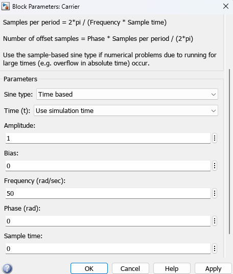
We now have the Carrier Signal and the Message signal! We now need to setup the Amplitude Modulated Signal. We will need to multiply the Carrier Signal and Message signal together to officially get the Amplitude Modulated Signal to be “Sent” to the destination.
Part 3: Creating the Amplitude Modulated Signal
Get a Product Block(The same way we got the Sine Wave Block, but search Product)
The two inputs of the product block will be the Message Signal Block, and the Carrier Signal Block.(ctrl + left-click the line to break off the section of the line).

We now have the Message Signal, Carrier Signal, and the Amplitude Modulated Signal. Now lets scope these signals to double-check if the signals are correct.
Part 4: Verifying Signals with scope
Get a Scope Block
Connect all 3 signals to the scope block(You should be able to add more than 1 input signal to the scope by simply dragging a line near the input of the scope.)
Double-Click the scope
Click the “View” tab and then clock “Layout”
It will show you a 4x4 matrix. Highlight 4x1 of the matrix.(4 rows and 1 columns)
Then Click “Simulation” -> “Run”.

We should be 3 signals for sure. The order of the signals will correlate to the input of the scope. In my instance I put the message sign first, Amplitude Modulated Signal second, and third is my Carrier Signal. Since this is an Amplitude Signal, the amplitude will vary depending on the Message Signal. Lets De-Modulate the Modulated Signal now!
Part 5: Demodulation of a Modulated Signal
In this example we will use products and transfer functions to demodulate the signal. Click and drag over 2 x Product Blocks, 2 x Transfer Function Blocks
The only parameters we will need to change are both of the Transfer Functions. Double-Click the Transfer Function Blocks and change Numerator Coefficients: 15, Denominator Coefficients: [1 15]. Click “Apply” and “OK”.
For one of the Product Blocks, Multiply the Modulated signal with the Carrier Signal.
As the output of that Product Block from c., connect both of the transfer functions in sequence with one another.
At the output of the last Transfer Function block multiply that output with a Constant Block of Value: 2
Connect the Product Block of e. to the scope.
Double-Click the scope and “Run” the scope.

In my case the, the fourth signal at the bottom is the demodulated signal. Which should be the same as the message signal.
Conclusion:
We first created our Message Signal and our Carrier Signal to be converted to a modulated signal. We then multiplied the Message Signal with the Carrier Signal to then create the Amplitude Modulated Signal. We scoped the signals to test and verify these signals are correct or valid. We then attempted to demodulate the signal using product of the modulated signals as well as transfer functions.
Problem:
With this lab we have the 4 signals: Message Signal, Amplitude Modulated Signal, Carrier Signal, and the demodulated signal of the amplitude modulated signal. Our demodulated signal is a little attenuated and out of phase. Some ideas of fixing this is using the Envolope Detector Demodulation method. As a Challenge for the user, how would you demodulate the signal to make it exactly the same as the original signal to ensure the user can receive a signal with a message without attenuation?